In-flow fluidelastic instabilities of tube bundles subjected to a two-phase flow.
Fluidelastic instability is the most important vibration excitation mechanism for heat exchanger, or steam generator type of tube bundles. It is so because of the very high vibrations amplitude that it can induce to the tubes which can lead to rapid failure by fatigue or wear. Also, unlike vibrations induced by vortex shedding (vortex-induced vibrations), fluidelastic instability is not a self limiting phenomenon: amplitude of vibrations does continue to increase with velocity past the critical onset of the instability. This is shown on Figure 1 for the case of single-phase flow.
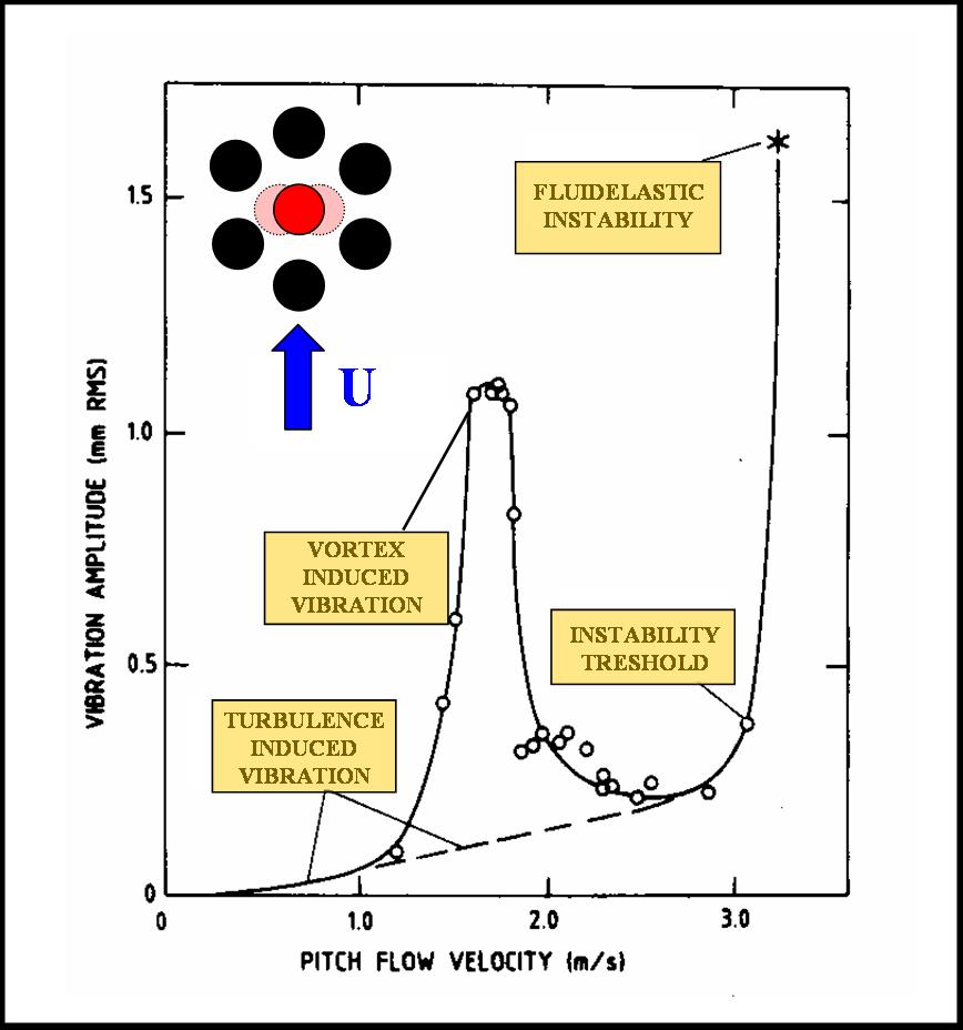
Figure 1 – Vibrations amplitude as a function of flow pitch velocity for a flexible cylinder in a rigid cluster (taken from Pettigrew et al. 1991). The cylinder is free to vibration in the cross-flow direction.
In nuclear power plant steam generators, U-tubes are very susceptible to undergo fluidelastic instability because of the high velocity of the two-phase mixture flow in the U-tube region and also because of their low natural frequencies in their out of plane modes. In nuclear power plant steam generator design, flat bar supports have been introduced in order to restrain vibrations of the U-tubes in the out of plane direction (see Figure 2). Since those supports are not as effective in restraining the in-plane vibrations of the tubes, there is a clear need to verify if fluidelastic instability can occur for a cluster of cylinders preferentially flexible in the flow direction.
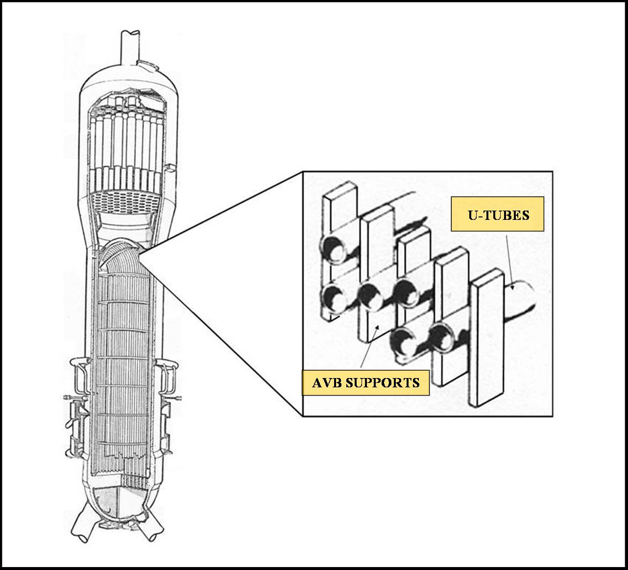
Figure 2 – Typical nuclear
power-plant steam generator with anti-vibration bars (AVB) or flat bar supports.
The experiments were performed in an air-water loop. The loop consist of a 30 l/s variable speed water pump, a magnetic flow meter, a 250 l/s air supply system, a 2500 l tank, a test section and connecting pipes as shown in Fig. 1.
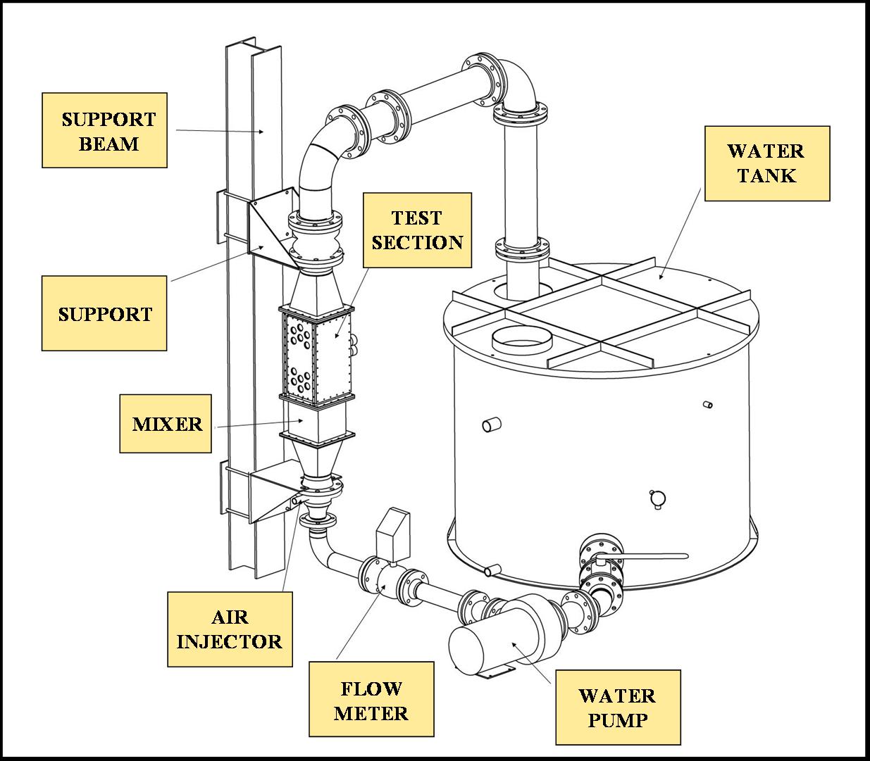
Figure 3 – Two-phase flow loop used in the BWC/AECL/NSERC industrial research chair of fluid and structure interaction at Ecole Polytechnique de Montréal.
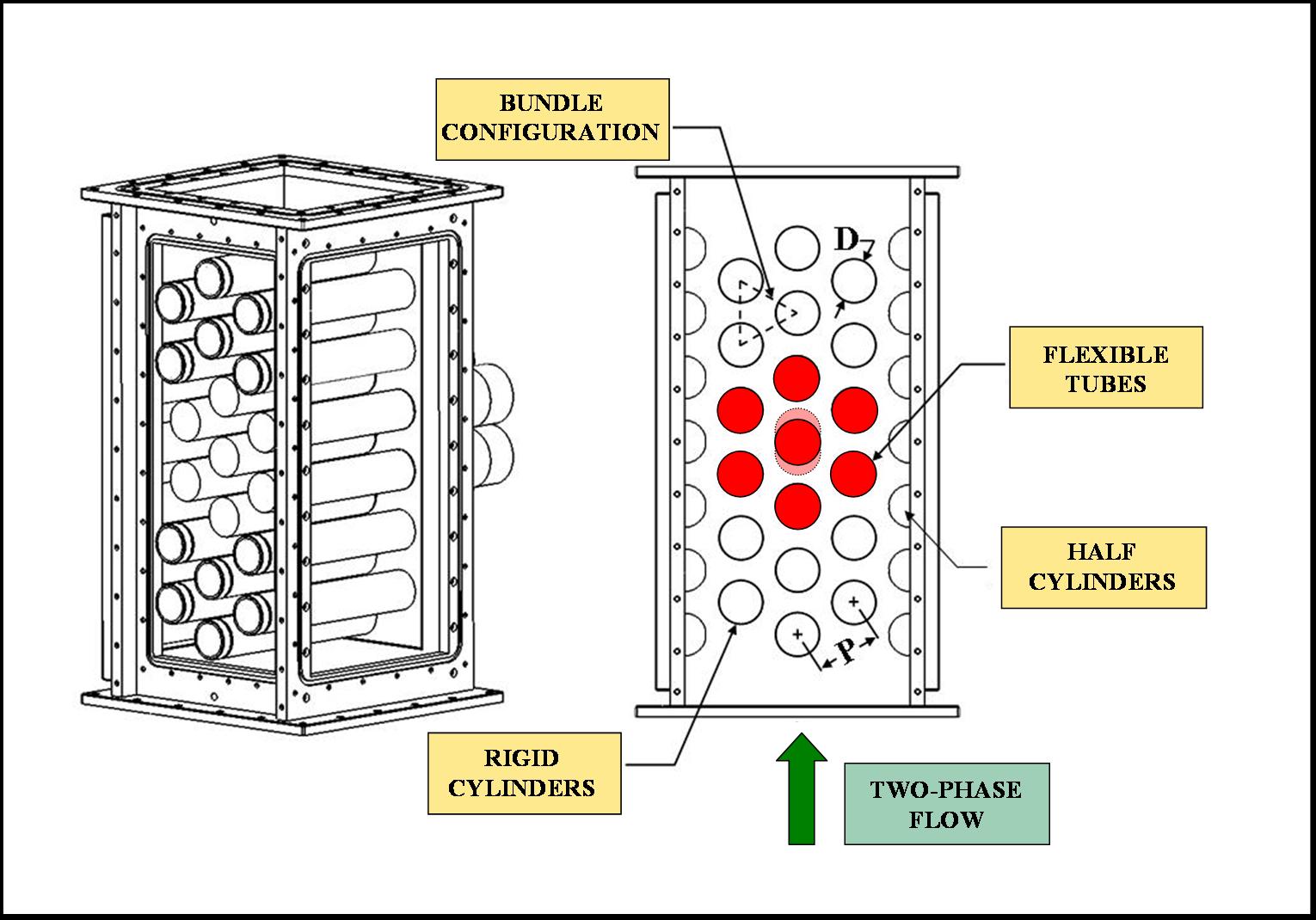
Figure 4 – Test section
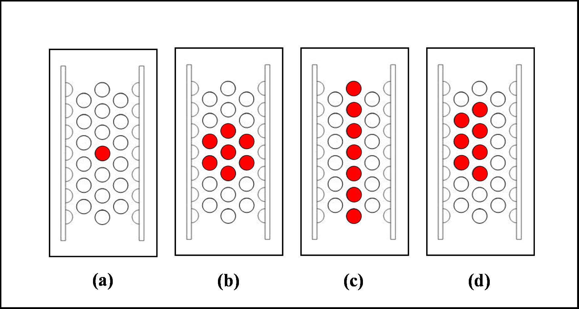
Figure 5 - Configurations of flexible tubes tested within the test section: (a) single flexible tube, (b) central cluster, (c) single flexible column, (d) two-partially flexible columns. Flow direction is upward.
Several
important conclusions
were drawn from the results of this research. First of all, fluidelastic
instability does occur for a bundle of cylinders preferentially flexible in the flow direction
in two-phase flow. Second, the observed
instability for the tubes flexible inflow occurred at higher flow
velocities than
axisymetrically flexible tubes. Third, no instability was observed for
the case
of the single flexible column. This is different than what was observed
in air
flow (reported by Mureithi et al. 2005). It was concluded that in high
void
fraction two-phase flow, flexible tubes must be located on at least two
adjacent
columns inside the bundle for fluidelastic instability to occur.
Detailed
information on this study can be found in Violette et al. 2006.
References
Mureithi, N.W., Zhang, C., and Pettigrew, M.J., Journal of Fluids and Structures, v. 21(1), pp. 75-87, 2005.
Fluidelastic Instability of Heat Exchanger Tube Bundles: Review and Design Recommendations
Pettigrew, M.J., Taylor, C.E., Journal of Pressure Vessel Technology, Vol. 113, pp.252-256, 1991.
BACK TO R. VIOLETTE WEBPAGE